I spent 3 weeks in my lab to create a 2 Node HYPER-V Failover Clusters with the Starwind VSAN to test , keep notes , monitoring the performance.
Most articles that read explain how to configure that StarWind VSAN with the Network/Storage Configuration and others how to configure only the Failover Clustering.
Here you can find an article which describe from scratch how to create and configure the HYPER-V Failover Clustering with StartWind VSAN and any configuration that must be done to works together these technologies.
So let's start !!
What is Software Define Storage (SDS)
Base on StarWind <<is a way in which software, rather than hardware, defines storage characteristics like performance, availability, and resiliency. Such programs are independent of the physical storage devices, which allows eliminating their limitations.>>
What is Failover Clustering
It's a group of Servers that works together to increate availability and scalability
Why to use Failover Clustering
For High Availability. Let's say that you have 40 Virtual Machines in one HYPER-V Server.
A morning comes in the office and realize that the HYPER-V Server is down and can't boot.
You have lost all your Servers. You have a backup and probably a Disaster Recovery Site.
How much time needs to be online and the users start to working??
Lab Design
Because i don't have the resources to use physical Servers and physical Storage the implementation done in a Virtual Environment
Physical HYPER-V Nodes
- 1 x Windows Server Datacenter Edition
- 1x NAS 2 TB
Virtual Environment for the Failover Cluster with StarWind VSAN
- 2 X Windows Server 2016 Core Standard Edition
- 1x 100GB Virtual Disk in both HYPER-V as the Storage for the Synchronization between the Nodes.
- 2 X Network Interfaces in every Node
- 5 X VLAN
- Cluster HB =192.168.52.0 for the Failover Cluster HB
- VM =192.168.53.0 for the Virtual Machines
- iSCSI = 192.168.54.0 for the Storage Synchronization between nodes Starwind Virtual SAN
- iSCSI HB = 192.168.57.0 for the iSCSI Heartbeat requested by Starwind Virtual SAN
- Management =192.168.50.0 for the Management
Network Configuration
As first step let's start to create and configure the Network Interfaces the will use in every Node:
It's absolute sure that will use Powershell for automation
Open the Powershell as administrator and run the following commands in both Nodes.
Note that the -VMName -Name -VlanId and the -Switchname should be change base on your environment
Add-VMNetworkAdapter -VMName srcl01 -Name iSCSI HB -SwitchName "New Virtual Switch"
Set-VMNetworkAdapterVlan -VMName srcl01 -VMNetworkAdapterName iSCSI HB -VlanId 57
Add-VMNetworkAdapter -VMName srcl01 -Name iSCSI -SwitchName "New Virtual Switch"
Set-VMNetworkAdapterVlan -VMName srcl01 -VMNetworkAdapterName Synchronization -VlanId 54
Add-VMNetworkAdapter -VMName srcl01 -Name Management -SwitchName "New Virtual Switch"
Set-VMNetworkAdapterVlan -VMName srcl01 -VMNetworkAdapterName iSCSI HB -VlanId 50
Add-VMNetworkAdapter -VMName srcl01 -Name VM -SwitchName "New Virtual Switch"
Set-VMNetworkAdapterVlan -VMName srcl01 -VMNetworkAdapterName iSCSI HB -VlanId 53
Add-VMNetworkAdapter -VMName srcl01 -Name Cluster HB -SwitchName "New Virtual Switch"
Set-VMNetworkAdapterVlan -VMName srcl01 -VMNetworkAdapterName iSCSI HB -VlanId 52
Next step to give Ip Addresses in every Network Interface
How to give IP Address from Powershell
Because i use Nested HYPER-V must identify which Network Adapter correspond in the VMNetworkAdapter.
If you have Physical Nodes you can start from the Step 5
- From the Physical HYPER-V Node run Get-vmnetworkAdapter -vmname SRCL01 to get a list of the Virtual Network Adapters in the Nested HYPER-V
- Now use the Enter-PSSession SRCL01 to open a session with Powershell in the Nested HYPER-V
- Type Get-NetAdapter to get a list of the Network Adapters inside the Nested HYPER-V Node
- Compare the MAC Addresses to identify the Network Adapters with the right VLAN

5. Now run the following command in every Network Interface to give the appropriate IP Address base on the VLAN Id.
6. Note that the -ifindex -IPAddress should be change base on your environment
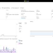
New-NetIPAddress -ifIndex 39 -IPAddress 192.168.57.1 -PrefixLength 24
Rename-NetAdapter -Name "Ethernet 11" -NewName "iSCSI HB"
[image]
- Only in the Management Interface Run the following command to add the Default Gateway
New-NetIPAddress -ifIndex 39 -IPAddress 192.168.50.1 -PrefixLength 24 -Default Gateway 192.168.50.254
[image]
How to give IP Address from Sconfig
If you would like to change the IP Addresses of the Network Interfaces with the sconfig follow the steps for every Network Interface
- Login in SRCL01
- Type sconfig
- Type the number 8 for the Network Settings

- Type the index number of the appropriate Network Interface

- Type 1 to Set Network Adapter Address

- Type S
- Enter the IP Address and press enter in the Subnet Mask and the Default Gateway.
- Remember only in the Management Interface must give the appropriate Default Gateway.

- Type 4 to Return in the Main Menu and proceed with the next Network Interface.
- Do it for all the Network Interfaces in both Nodes
Storage Configuration
I write down how to configure the Storage if you have Physical Server or Nested HYPER-V Server respectively.
So let's do it !!!
How to configure the Storage in Physical HYPER-V Nodes
If you have Physical Servers then you only need to create the RAID base on the requirements of Starwind Recommended RAID settings for HDD and SSD disks
How to configure the Storage in Nested HYPER-V Nodes
In the Nested HYPER-V Nodes required a few more steps to create the Virtual Disks in every Node hat will store the Images of the Starwind VSAN
So let's start to create the Virtual Hard disks
- Login in the Physical HYPER-V which Host the Nested HYPER-V and open the Powershell as Administrator
- Run the following commands to create the Virtual Disks in every HYPER-V Node
New-VHD -Path "D:\SRCL01\data1.vhdx" -SizeBytes 20gb -Fixed

- After the disk created run the command to added in the Node SRCL01
Add-VMHardDiskDrive -VMName srcl01 -Path "D:\SRCL01\data1.vhdx" -ControllerType SCSI -ControllerLocation 2
- You can verify that the disk added in the right Node with the command
Get-VMHardDiskDrive -VMName srcl01

- Login in first Node SRCL01 to initialize the Disks
- Run powershell
- Before initialize the disks in the Virtual Machine that are in RAW PartitionStyle
- Run the powershell command to identify the new disk
Get-Disk | Where-Object PartitionStyle -Eq 'RAW'
- Now run the Powershell command to initialize , format and give a Letter in the Disk
- Not the the -Number and -DriveLetter may vary in your environment
Get-Disk –Number 2 | Where-Object PartitionStyle –Eq 'RAW'| Initialize-Disk -Passthru| New-Partition –DriveLetter F -UseMaximumSize |Format-Volume -FileSystem NTFS -Confirm:$false -Force
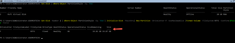
- Verify the new disk with the Powershell command Get-Disk
Startwind VSAN
StarWind VSAN must be install in every Node.
If you use Windows Server Core Edition then the StarWind VSAN Management Console must be install in other Server
StarWind it's not support StarWind VSAN Management Console in a Windows Server Core Edition..
How to install the Starwind VSAN in the Nodes
Do you finish with the Network and Storage Configuration?
Then it's time to proceed with the Starwind VSAN installation in every HYPER-V node
You can find different ways to install but i will explain the traditional one.
- Download the application from StarWind Site
- Copy the file in the SRCL01
- Login to SRCL01, browse with the cd command in the path that you copy the file
- type .\starwind_v8.exe
- Tick the I accept...

- Read the Information and click Next

- Uncheck the Starwind Management Console and click Next

- Select the Start Menu Folder and click Next

- Check the Thank you I have do a key already.

- Click Browse and find the License Key

- Read the Details of the Key and click Next

- Click Install to proceed with the installation

- Base on Starwind you must open the file Starwind.cfg from C:\Program Files\StarWind Software\StarWind.
- Find the iScsiDicoverylistinterfaces value=0 and change the value to 1

- Restart the Starwind Service
How to install the Starwind VSAN Management Console
Because in the scenario we use Windows Server 2016 Standard Core Edition we must install the Starwind Management Console in other Server.
In any case this is your decision if you use Windows Server 2016 Standard GUI Edition
- Follow the same steps as in the Starwind installation
- The only difference is to Select only the Starwind Management Console and the Powershell Management Library in the Select Components

How to Add the Servers in the Starwind Management Console
- Open the Starwind Management Console and click Add Server

- Type the Ip Address of the first HYPER-V Node and click OK

- You will see the Server in the left side
- Right click and select Connect

- Do the same for the other Node
iSCSI Connections
After create and initialize the Virtual Disks the next step is to create the iSCSI Connections and Targets in the 2 Nodes
How to create the iSCSI Connections with Powershell
In order to have the Synchronization between the Storage in both nodes we must create the iSCSI Connections between them.
Run the following steps in both node respectively
In the first HYPER-V node
- Run the Powershell command to create the iSCSI Connection to itself
New-IscsiTargetPortal -TargetPortalAddress 192.168.54.1 -TargetPortalPortNumber 3260
- Run the Powershell command to create the iSCSI Connection with the partner HYPER-V node
New-IscsiTargetPortal -TargetPortalAddress 192.168.54.2 -InitiatorPortalAddress 192.168.54.1 -TargetPortalPortNumber 3260

- Now run the command to connect the iSCSI
- The -isPersistent use it to autoconenct after a reboot.
- Don't forget it because if don't use it in the next restart the iSCSI will not connect with the Nodes and all the VM's will be down
Get-IscsiTarget | Connect-IscsiTarget -IsPersistent $true -IsMultipathEnabled $true

How to create the iSCSI Connections with iSCSI Gui
If you want to proceed with iSCSI GUI then
- In the first HYPER-V Node SRCL01 run the command iscsicpl.exe
- Go in the Tab Discovery
- Click Discover Portal
- Type the ip address of the iSCSI Adapter.
- In my Server is the 192.168.54.1
- Click Advance

- In the Local Adapter select the Mirosoft iSCSI initiator
- In the Initiator IP leave it as Default.

- Click once Discovery Portal
- Type the Ip Address from the Network Adapter which use it for the iSCSI of the Partner HYPER-V Node
- In my Server is the 192.168.54.2
- Click Advance
- In the Local Adapter select the Microsoft iSCSI initiator
- In the Initiator IP select the Ip Address of the Partner HYPER-V Node which is the 192.168.54.1 in this environment.

How to Connect the iSCSI Targets
Click in the Tab Targets to see the available targets.
It must be 4 targets
- 2 for the witness in every partner
- 2 for the storage in every partner

Let's proceed to connect the witness targets.
Follow these steps for every witness target
- Select one of the witness targets and click Connect
- Check the Enable Multipath
- Click in Advance button

- For the Witness it's recommended to connect only in the local server and not in the partner Node
- The Local Adapter must be the Microsoft iSCSI Initiator
- The Initiator IP must be Default
- The Target IP must be the IP Address for the Storage (iSCSI Vlan) of the Local Server.

Now let's connect the other targets
Follow the steps for every target
- Select one of the targets and click Connect
- Check the Enable Multipath
- Click in Advance button

- The Local Adapter must be the Microsoft iSCSI Initiator
- The Initiator IP must be the IP Address for the Storage (iSCSI Vlan)
- The Target IP must be the IP Address for the Storage (iSCSI Vlan) of the Partner HYPER-V Node.

How to Configure the Multipath I/O
Starwind recommends to use Failover Only or Least Queue Depth MPIO Policy for 1GBit Network Cards and the Round Robin for 10Gbit Network cards
- In every Target click in Devices

- Click on MPIO

- Change the Policy base on your Network Cards
- In this scenario i use Failover Only
- Note that for the Witness targets must use only Failover Only Policy

How to Initialize the Disks
After you have connect all the Target you must initialize the Disks in every HYPER-V Node
Follow the steps for every HYPER-V Node
- Login in SRCL01
- Type powershell
- Type Get-Disk
- Run the powershell command to initialize the disk
Get-Disk –Number 2 | Where-Object PartitionStyle –Eq 'RAW'| Initialize-Disk -Passthru| New-Partition –DriveLetter F -UseMaximumSize |Format-Volume -FileSystem NTFS -Confirm:$false -Force

- Type once again Get-Disk to verify that the Disks are online

How to Create the High Availability between the Nodes
Because we use the StartWind VSAN free Version you must do all the Configuration from the Powershell
Starwind has create lot of scripts that can help you for the configuration.
- Open the Powershell ISE as Administrator
- Open the C:\Program Files\StarWind Software\StarWind\StarWindX\Samples\powershell
- Find out and edit the CreateHA_2
- Copy/Paste the code in Powershell_ISE
- Do the following changes base on your environment
- $addr and $addr2 = Ip Address of the HYPER-V Nodes
- $imgepath = The path that will store that image
- $imagename = The name of the image
- $targetalias = the targetalias
- $syncinterface = The ip address of the partner interface in iSCSI VLAN
- $hbinterface = The ip address of the partner interface in iSCSI HB VLAN
- Run the script

How to install HYPER-V Role
We finished with the configuration and now we will proceed with easier tasks
Let's install the HYPER-V Role in both Nodes
- From the Device that Manage the Nodes open a powershell as Administrator
- Run the following command
Invoke-command -ComputerName SRCL01,SRCL02 -ScriptBlock {Install-WindowsFeature -Name hyper-v -IncludeAllSubFeature -Restart}
How to install Failover Clustering
Let's install the Failover Clustering Role
- From the Device that Manage the Nodes open a powershell as Administrator
- Run the following command
Invoke-Command -ComputerName srcl01,srcl02 -ScriptBlock {Install-WindowsFeature -Name Failover-Clustering -IncludeAllSubFeatur
e -Restart}
How to Validate the Configuration for the Clusters
After install the Failover Clustering Role the first step is to Validate the Configuration to begin to use Failover Clustering.
The Validation is a Test for the Network , Storage Configuration , Hardware and more of the Nodes .
When finish the Validation you will get a Report to see the Results
If it will not pass then you must find the errors fro the Report and proceed to resolve it.
- From the Management Device open the Failover Clustering Console
- Click in Validation Configuration

- Just click Next
- Type the Names of the HYPER-V Failover Clusters one by one and click Add

- Leave the Run all the Tests

- It's a confirmation. You can see the tests that will run

- Wait until finish and get the Report.
- Note that it will takes a few minutes
- If it pass the test the you can check the Create the Clusters now using the Validation nodes...

- Click Next

- Type the Cluster Administrative name and give an Ip Address.

- Leave with the Default options and click Next

- Click Finish to create the Clusters

How to configure the Networks in Failover Cluster Manager
- Open the Failover Cluster Manager
- Expand the Failover Administer Name
- Click on Networks
- From the right side click on every Network Name
- See the Subnets in the bottom and rename the Network with the appropriate Name for better management.

- In the right side click on Live Migration Settings
- Select the Network that must use the Live Migration.

- It's recommended to use a dedicate network for the Live Migration traffic.
- If you don't have a separate network for the Live Migration use the Cluster HB.
How to Add Storage in the Failover Cluster
It's time to add the Storage that we create in the beginning
- From the Failover Cluster Console
- Expand the Storage
- Right click in Disk. Select Add Disk
- Check all the Disks which appear. Click OK

- If you have follow the Steps you will have 2 disks.
- One Disk for the VM's and one for the Quorum Witness
- Identify the Disk which created for the VM's
- Right click and select Add to Cluster Shared Volumes

Remember that the Disk which create for the Quorum Witness must not add in the Cluster Share Volume
How to configure Quorum Witness
It's time to configure the Quorum Witness
- Right click in the Failover Administer Name
- Select More Actions -- Configure Cluster Quorum Settings

- Click Next in the first step

- Click in option Select the quorum settings

- Select the Configure disk witness

- Select the appropriate disks

- Read the configuration before proceed

- Click Finish
- Now go in the Storage -- Disks
- In the Assign To you will see where every disk belongs.

Now you can start to create Virtual Machines in your 2-Node HYPER-V Failover Clusters with StartWind VSAN
Maybe you will find complex or so many steps to Build 2 Nodes in Failover Clustering with Starwind VSAN but you will have lot of advantages and eliminate the single point of failure in every device.
If you think that it's will take lot of time and it's not worth it THEN think first WHICH will be the IMPACT if your Storage or the single HYPER-V failed in your production environment.
Have a nice weekend !!!